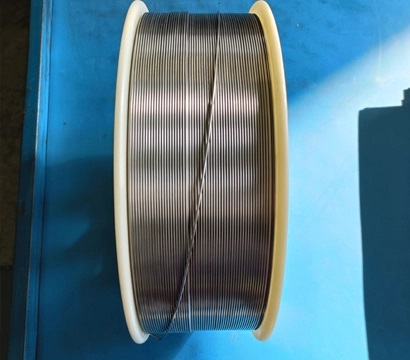
Repairing a cracked cast iron engine block or machine housing requires more than simply filling the damaged area with weld metal. Cast iron contains a relatively high carbon content and has limited ductility, making it vulnerable to hard heat-affected zones, residual stress and cracking during rapid heating or cooling. For gray cast iron components that require machining after repair, a pure nickel Z308 nickel welding rod is commonly selected because its deposited metal offers good machinability and helps accommodate welding contraction. A successful repair still depends on correct material identification, crack removal, cleaning, controlled heat input, short weld beads, stress relief and slow cooling. Safety-critical or pressure-bearing castings should only be repaired under an approved welding procedure and qualified engineering supervision.
Why Is Cast Iron Difficult to Weld?
Gray cast iron contains carbon in the form of graphite flakes. During welding, the concentrated arc heat can alter the microstructure around the fusion line and heat-affected zone. If this area cools too rapidly, it may form hard and brittle structures that are susceptible to cracking.
Cast iron also has much lower ductility than ordinary structural steel. The surrounding cold metal restricts the expansion of the heated weld area, while contraction during cooling introduces tensile stress. Because the base material cannot easily deform to relieve this stress, cracks may form in the weld, beside the weld or at the ends of the original defect.
According to TWI guidance on welding cast iron, cleaning, controlled heating and cooling, suitable nickel consumables and careful stress management are important for reducing cracking risk.
Main Sources of Cast Iron Weld Failure
Incorrect identification of the cast iron grade or component condition
Oil, paint, carbon, rust or other contaminants remaining in the joint
Failure to remove the full depth of the original crack
Excessive welding current or long continuous weld beads
Large temperature differences between the weld area and the casting
Rapid cooling after welding
Excessive restraint in a thick, rigid or complex casting
Using an electrode that produces a hard, non-machinable deposit
When Should You Use Z308 Welding Rod?
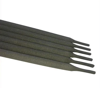
Z308 is a nickel-based cast iron electrode primarily intended for repair welding of gray cast iron. It is especially useful when the repaired area must remain machinable after welding or when a softer, more ductile weld deposit is preferred.
Minghua Z308 uses a pure nickel core wire and a graphite-type coating. The deposited metal is designed to provide good machinability and crack resistance for selected gray cast iron repair applications. The electrode can be used with AC or DC+ according to the recommended welding parameters and the approved repair procedure.
Typical Z308 Applications
Cracked gray cast iron engine blocks
Machine tool beds and machine bases
Pump housings and gearbox housings
Engine seats and bearing seats
Gear seats and mounting surfaces
Thin cast iron components
Machined surfaces requiring drilling, milling or grinding after repair
Local casting defects and worn areas in gray iron components
Z308 should not automatically be used for every cast iron grade or every structural repair. Ductile iron, malleable iron, high-strength cast iron and heavily restrained thick castings may require a nickel-iron electrode, another filler system or a specially qualified procedure.
For a broader comparison, review the Z308 vs. Z408 vs. Z208 cast iron welding rod selection guide.
| Repair Condition | Is Z308 Suitable? | Selection Consideration |
|---|---|---|
| Gray cast iron requiring post-weld machining | Generally suitable | Z308 provides a relatively soft and machinable nickel deposit. |
| Thin gray cast iron component | Generally suitable | Use controlled heat input and short weld beads. |
| Engine block crack | Conditionally suitable | Confirm crack location, casting condition, service load and leak-tightness requirements. |
| Machine housing or machine base | Generally suitable | Suitable when dimensional stability and machining are important. |
| High-load ductile iron component | Requires engineering review | A nickel-iron electrode or another procedure may be more appropriate. |
| Pressure-bearing or safety-critical casting | Qualified procedure required | Use an approved WPS, qualified welder and specified inspection method. |
| Unknown cast iron grade | Do not select by appearance alone | Identify the material and evaluate weldability before repair. |
Assess the Engine Block or Machine Housing Before Welding
The decision to weld should be made only after the damaged casting has been inspected. Some cracks extend farther than they appear on the surface, and contamination inside an engine block or gearbox housing can make fusion welding unreliable.
1. Identify the Base Material
Confirm whether the component is gray cast iron, ductile iron, malleable iron, compacted graphite iron or cast steel. Original equipment documentation, material certificates, chemical analysis or metallographic examination provide more reliable identification than visual inspection alone.
TWI notes that consumable selection depends on the type of cast iron and the required properties of the repaired area. Pure nickel fillers are commonly used for gray iron repairs requiring a soft and machinable deposit, while nickel-iron fillers may be selected for higher-strength gray iron, ductile iron or dissimilar joints. See the TWI cast iron consumable selection guide.
2. Determine Whether the Component Is Safe to Repair
Evaluate the crack location, wall thickness, operating temperature, load, vibration, internal pressure and consequences of failure. Welding may not be appropriate when the crack affects a highly stressed bearing area, main structural web, combustion chamber, cylinder bore or another safety-critical region unless the repair is approved by the component manufacturer or a qualified engineer.
3. Locate the Full Crack
Clean the area and use a suitable nondestructive testing method to identify the crack ends and any branches. Dye penetrant testing is commonly used for surface-breaking defects, while additional methods may be required depending on the geometry and acceptance criteria.
Grinding out only the visible center of the crack can leave damaged material at both ends. The crack should be completely removed or controlled according to the approved repair plan before welding begins.
4. Check for Oil and Carbon Contamination
Engine blocks, pump housings and gearbox housings may absorb oil into the porous casting surface. Oil, grease, paint, rust and graphite residue can cause porosity, unstable arc behavior and lack of fusion. Severely oil-soaked castings may require repeated cleaning and controlled heating before they can be welded successfully.
Z308 Electrode Diameter and Reference Welding Current
Electrode diameter should be selected according to the casting thickness, groove size, welding position and heat-input limitations. The following values are reference parameters currently published for Minghua Z308. The final settings must be confirmed against the latest product TDS, repair WPS and actual welding conditions.
| Electrode Diameter | Reference Current | Power Supply | Typical Selection Consideration |
|---|---|---|---|
| Φ2.5 mm | 60–100 A | AC or DC+ | Thin sections, small grooves and localized repair |
| Φ3.2 mm | 90–120 A | AC or DC+ | General engine block and machine housing repair |
| Φ4.0 mm | 130–180 A | AC or DC+ | Larger groove volume and thicker castings where heat can be controlled |
| Φ5.0 mm | 160–190 A | AC or DC+ | Large repairs under a qualified procedure |
Avoid selecting a higher current only to increase deposition speed. Excessive current increases dilution, enlarges the heat-affected zone and may increase thermal stress. Start within the approved range and use the lowest stable current that provides adequate fusion.
Step-by-Step Process for Repairing Cast Iron with Z308
The following process is a general technical framework rather than a replacement for a qualified welding procedure. Actual parameters must be adjusted according to the casting grade, thickness, crack position, restraint and service requirements.
Step 1: Disassemble and Degrease the Component
Remove seals, bearings, gaskets, paint, oil and other components that may be damaged by heat. Degrease the repair area thoroughly. Engine blocks and oil-containing housings may require repeated cleaning because contamination can migrate back to the surface during heating.
Use an appropriate solvent and follow the applicable workplace safety requirements. Do not weld until flammable residues and cleaning chemicals have been completely removed.
Step 2: Stop and Remove the Crack
Mark the complete crack path using the selected inspection method. Where the approved repair procedure calls for it, drill small stop holes beyond the crack ends to reduce further propagation during groove preparation.
Grind or machine the crack into a suitable U-groove or open groove. A smooth groove profile is generally preferred over a sharp V-shaped root because sharp corners concentrate stress. Remove the crack completely and avoid leaving thin, unsupported edges.
Step 3: Clean the Groove to Sound Metal
Remove all grinding dust, graphite, oxide, paint and oil from the groove and adjacent surface. Use tools reserved for cast iron or nickel welding where possible to prevent cross-contamination.
TWI recommends removing the casting skin and residual surface graphite from the welding area. Light, controlled heating may also help release moisture or oil trapped near the repair zone, but the component must be allowed to stabilize before welding.
Step 4: Choose Cold Welding or Controlled Preheating
Two broad methods are used for cast iron repair:
Cold or low-heat repair: Uses short, intermittent weld beads and controlled interpass temperature to minimize total heat input and distortion.
Preheated repair: Heats part or all of the casting slowly and uniformly to reduce the temperature gradient between the weld area and the surrounding metal.
“Cold welding” does not mean that no heat enters the casting. It means that the total heat input and local temperature rise are deliberately limited. The choice between cold repair and preheating must be based on the casting size, geometry, restraint, crack location and approved procedure.
For some castings, slow and uniform preheating reduces the thermal gradient and residual stress. However, applying intense local heat to only one small area of a large rigid casting can increase distortion or create new cracks. TWI reports that typical minimum preheat temperatures can vary widely according to the cast iron grade and acceptable heat-affected-zone hardness, so a single universal preheat temperature should not be applied to every repair.
Step 5: Tack and Sequence the Repair
On long cracks, consider a balanced welding sequence rather than progressing continuously from one end to the other. Short, separated weld sections can help distribute heat and reduce accumulated contraction.
When alignment is critical, verify dimensions before welding and use fixtures carefully. Excessively rigid clamping can prevent natural contraction and increase cracking stress.
Step 6: Deposit Short Stringer Beads
Strike the arc on prepared metal and use short stringer beads rather than wide weaving. Keep each bead short enough to prevent excessive heat buildup. The appropriate bead length depends on the casting and procedure; do not rely on a fixed length for every component.
Use a controlled travel speed and avoid excessive penetration into the cast iron. Too much base-metal melting increases dilution and may produce a harder fusion zone. Clean slag completely before depositing the next bead.
Lincoln Electric also recommends selecting nickel-type cast iron electrodes when the repaired area must be machined and emphasizes controlling the welding technique according to the casting and electrode. See its guidelines for welding cast iron.
Step 7: Peen the Weld Bead When Appropriate
Light peening may be used on a still-warm, ductile nickel weld bead to introduce compressive stress and help offset contraction. Use controlled, moderate blows with a suitable rounded hammer. Do not aggressively hammer the fusion boundary or the brittle cast iron base material.
Peening is not a substitute for correct heat control, joint preparation or filler selection. It should only be used when permitted by the repair procedure.
Step 8: Control Interpass Temperature
Allow the weld area to cool between short deposits when using a low-heat repair method. Avoid allowing the entire casting to become progressively hotter with every pass. Temperature crayons, infrared measurement or contact thermometers may be used when the procedure specifies an interpass limit.
Step 9: Fill and Finish the Groove Gradually
Continue the staggered bead sequence until the groove is filled. Avoid excessive reinforcement, which creates more grinding work and additional localized heating. Where machining is required, leave only the necessary allowance for final dimensional restoration.
Step 10: Cool the Casting Slowly
Rapid cooling increases thermal stress and can promote cracking. After welding, protect the component from drafts, cold floors and water. Depending on the approved procedure, slow cooling may be achieved with an insulating blanket, dry sand, vermiculite, a controlled furnace or another suitable insulating method.
Do not quench the repaired casting. Allow sufficient time for the entire component to return gradually to ambient temperature before machining or final inspection.
Repairing Engine Blocks vs. Machine Housings
Although both components may be made from gray cast iron, their repair priorities are different.
| Repair Factor | Cast Iron Engine Block | Machine Housing or Machine Base |
|---|---|---|
| Common Damage | Freeze cracks, coolant leaks, impact cracks, damaged mounting areas | Fatigue cracks, impact damage, worn seats, broken mounting sections |
| Contamination Risk | High due to oil, coolant, combustion residue and corrosion | Moderate to high due to oil, grease and process contamination |
| Dimensional Requirement | Critical around bores, decks, seats and sealing surfaces | Critical around bearings, shafts, guideways and mounting faces |
| Leak-Tightness Requirement | Often required for water or oil passages | Depends on whether the housing retains oil or process fluid |
| Machining After Welding | Frequently required | Frequently required on precision seats and guide surfaces |
| Key Repair Risk | Hidden cracks, porosity, leakage and distortion | Misalignment, residual stress and loss of dimensional accuracy |
Special Considerations for Engine Blocks
Engine blocks contain complex internal passages, thin walls, machined sealing surfaces and highly loaded regions. Before welding, the repair team should determine whether the crack connects with a coolant passage, oil gallery, cylinder bore, main bearing web or combustion-related area.
After welding, the block may require pressure testing, surface machining, dimensional inspection and crack detection. A visually acceptable bead does not prove that the repair is leak-tight or structurally suitable.
Special Considerations for Machine Housings
Machine housings and machine bases often depend on accurate alignment between bearing bores, shafts, guides and mounting faces. Heat distortion can make a repair unusable even when no new cracks are visible.
Before welding, record critical dimensions and determine whether machining allowance is available. For large housings, a balanced repair sequence and rigid dimensional inspection plan are often more important than deposition speed.
Common Mistakes When Welding Cast Iron with Z308
Using Z308 Without Identifying the Casting
Z308 is commonly used for gray cast iron, but not every dark-colored casting is gray iron. Ductile iron, cast steel and specialized alloy castings may require different consumables and procedures.
Welding Over Oil-Soaked or Graphite-Contaminated Metal
Surface cleaning alone may not remove contamination absorbed into the casting. Porosity that repeatedly appears in the weld is often a sign that further cleaning or controlled contaminant removal is required.
Depositing Long Continuous Beads
Long beads introduce more heat and contraction into a brittle casting. Short, controlled deposits with an appropriate sequence generally provide better stress management.
Using Excessive Current
High current increases penetration and dilution. It may make the arc feel easier to operate, but it can enlarge the hard heat-affected zone and increase the risk of cracking.
Cooling with Water or Compressed Air
Forced cooling creates severe temperature gradients. Cast iron repairs should generally be cooled gradually under controlled conditions.
Machining Before the Casting Has Fully Stabilized
The repaired component should return to a stable temperature before dimensional inspection or machining. Machining too early can produce inaccurate dimensions or reveal delayed cracking after the work is completed.
Skipping Final Inspection
Grinding the bead smooth does not confirm repair quality. The completed component should be inspected according to its service requirements, including surface crack testing, dimensional measurement or leak testing where applicable.
How to Inspect a Completed Z308 Cast Iron Repair
The required inspection method depends on the importance and function of the component. A general inspection plan may include:
Visual inspection: Check bead profile, undercut, incomplete filling, slag and visible surface cracks.
Dye penetrant testing: Detect surface-breaking cracks around the weld and heat-affected zone.
Dimensional inspection: Measure bearing seats, mounting faces, guide surfaces and alignment points.
Leak testing: Pressure-test coolant passages, oil chambers or sealed housings where required.
Machining evaluation: Confirm that the deposited metal can be machined to the specified finish and dimension.
Service review: Verify that the repaired component is suitable for its original load, temperature, vibration and operating environment.
Safety-critical components may require a formally documented repair procedure, welder qualification, inspection records and engineering approval before being returned to service.
How to Source Z308 Welding Rod for Industrial Repair
Buyers should not evaluate a cast iron electrode by product name alone. Before placing an order, confirm:
Electrode core and deposited-metal composition
Available diameters and electrode lengths
Recommended AC or DC polarity
Reference current range for each diameter
Packaging and moisture-protection method
Batch chemical composition or inspection documents
Machinability requirements after welding
Base material and actual component application
Required quantity, delivery time and export packaging
Minghua supplies multiple cast iron welding rods for different repair conditions. Buyers can provide casting type, wall thickness, crack location, machining requirements and service conditions so that the appropriate electrode and diameter can be evaluated.
Frequently Asked Questions About Z308 Cast Iron Repair
Can Z308 welding rod be used to repair a cast iron engine block?
Z308 can be used for selected gray cast iron engine block repairs, particularly where the deposited metal must remain machinable. The crack location, contamination, wall thickness, service load and leak-tightness requirements must be evaluated before welding. Safety-critical areas require an approved repair procedure.
Is preheating required when welding cast iron with Z308?
Not every Z308 repair uses the same preheat temperature. Some repairs use a low-heat or cold-welding method with short intermittent beads, while others benefit from slow and uniform preheating. The correct method depends on the casting grade, size, restraint and approved WPS.
Why are short weld beads used on cast iron?
Short beads limit localized heat buildup and welding contraction. They allow the casting to cool between deposits and help reduce the residual stresses that can cause cracking.
Can Z308 weld metal be machined after repair?
Z308 is selected for many gray cast iron repairs because its nickel-rich deposited metal provides better machinability than deposits produced by many iron-based electrodes. Actual machinability still depends on dilution, heat input, base material and repair technique.
Can Minghua Z308 be used with AC and DC welding machines?
According to the current Minghua product information, Z308 can be used with AC or DC+. The current should be selected according to electrode diameter and confirmed against the latest product TDS and welding procedure.
What is the difference between Z308 and Z408?
Z308 is a pure nickel-type electrode commonly selected for gray cast iron repairs requiring good machinability. Z408 is a nickel-iron-type electrode generally considered when higher deposited-metal strength and toughness are required. Final selection depends on the casting grade and service condition.
How should a repaired cast iron component be cooled?
The component should generally cool gradually and evenly. Depending on the qualified procedure, insulation blankets, dry sand, vermiculite or controlled furnace cooling may be used. Water quenching and strong forced-air cooling should be avoided.
Final Recommendations
Z308 welding rod is a practical option for repairing gray cast iron engine blocks, machine housings and precision cast components when machinability and controlled crack resistance are important. However, electrode selection alone cannot guarantee a successful repair.
Start by identifying the casting and determining whether welding is technically and economically appropriate. Remove the entire crack, eliminate contamination, use controlled heat input, deposit short stringer beads, manage contraction and allow the casting to cool slowly. Complete the repair with suitable crack detection, dimensional inspection and leak testing where required.
For product specifications, available diameters, packaging or application support, review the Minghua Z308 cast iron electrode or contact Minghua with your base material, component photos, crack dimensions and post-weld machining requirements.