Welding electrode manufacturing transforms a prepared metal core wire and a controlled flux formulation into a consistent, traceable consumable. A typical process includes raw-material inspection, core-wire preparation, flux batching and mixing, coating extrusion, eccentricity control, drying, product testing, printing and packaging.
The exact equipment, binder system, drying cycle and quality tests depend on the electrode classification being produced. Rutile, basic low-hydrogen, stainless steel, hardfacing and cast-iron electrodes cannot all be manufactured with one universal recipe or process setting.
Content Updated: August 2026
Technical Scope: This guide explains the general production flow for flux-coated welding electrodes. Individual formulations, equipment parameters and acceptance tests must follow the applicable specification, qualified manufacturing procedure and product requirements.
Welding Electrode Manufacturing Process at a Glance
| Stage | Main Operation | Primary Control Point |
|---|
| 1 | Incoming material inspection | Wire chemistry, diameter, powder identity and batch condition |
| 2 | Core-wire preparation | Diameter, straightness, cut length and surface cleanliness |
| 3 | Flux batching and mixing | Recipe accuracy, ingredient distribution and mix consistency |
| 4 | Briquetting and coating extrusion | Coating pressure, thickness, adhesion and concentricity |
| 5 | Finishing and in-line inspection | Grip end, striking end, surface defects and eccentricity |
| 6 | Drying or baking | Product-specific time, temperature profile and final moisture |
| 7 | Testing and classification verification | Dimensions, usability and required weld-metal properties |
| 8 | Printing, packing and traceability | Identity, lot code, package integrity and storage condition |
What Materials Are Used to Make Welding Electrodes?
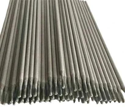
A covered electrode consists of a metal core wire surrounded by a formulated coating. The wire carries welding current and contributes metal to the weld. The coating can provide shielding gases, slag formation, arc stabilization, deoxidation, alloying additions and usability characteristics.
Typical coating ingredients may include minerals, carbonates, silicates, cellulose-bearing materials, metal powders, ferroalloys, deoxidizers and binders. The exact formulation is product-specific and affects arc behavior, slag removal, weld-metal chemistry, deposition efficiency and moisture sensitivity.
Different formulations serve different welding processes, base metals and applications. For a broader classification overview, see our guide to types of welding electrodes and their uses.
Step 1: Inspect the Core Wire and Coating Materials
Manufacturing control begins before material enters the production line. The core wire should be checked against the required chemistry, diameter, surface condition and batch documentation. Coating ingredients should be verified for identity, particle condition, moisture status and lot traceability.
Substituting a powder, alloy addition or binder without technical evaluation can change extrusion behavior and final weld performance. Controlled storage and batch identification therefore matter as much as the downstream machine settings.
Step 2: Prepare the Electrode Core Wire
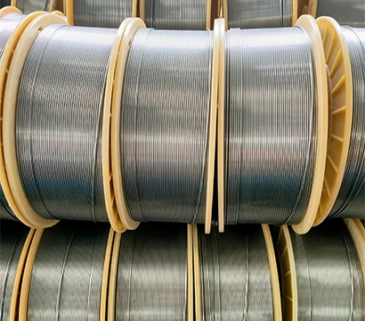
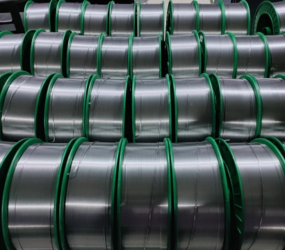
When production begins with wire coil, the wire may pass through drawing or sizing, straightening and cutting operations. Plants that purchase prepared cut wire can begin with incoming inspection and feeding instead. The required equipment therefore depends on the chosen raw-material starting point.
Control wire diameter and dimensional consistency.
Straighten and cut the wire to the specified electrode length.
Remove surface contamination that could reduce coating adhesion.
Separate or investigate bent, damaged or out-of-tolerance wire.
Step 3: Batch and Mix the Flux Coating
Flux ingredients are weighed according to the approved formulation. Dry mixing distributes powders and alloy additions before the specified liquid binder is introduced. Wet mixing then develops a consistent mass suitable for briquetting and extrusion.
Mixing time, sequence, binder addition and temperature can affect plasticity, coating adhesion and extrusion pressure. Too little binder may produce cracking or poor adhesion; excessive or uneven liquid addition can change coating geometry and drying behavior.
Process control: Use controlled formulations, calibrated weighing equipment and batch records. The coating recipe should not be adjusted only to make extrusion easier without evaluating weld-metal and classification requirements.
Step 4: Briquette and Extrude the Coating
The prepared coating mix may be compacted into briquettes or charges that can be fed consistently into the coating machine. During extrusion, the core wire passes through the coating head while the flux mass is applied around it under controlled pressure.
The objective is not merely to cover the wire. The process must maintain the specified coating thickness, smoothness, adhesion and concentricity. A coating that is visibly acceptable but significantly eccentric may melt unevenly and affect arc behavior.
Manufacturers planning this stage can compare screw-type and hydraulic configurations on the welding rod making machine page. Machine selection should be based on the formulation, diameter range, output and automation requirement rather than a generic capacity claim.
Step 5: Finish the Electrode and Check Eccentricity
After coating, the electrode is conveyed through finishing operations. The grip end must expose enough core wire for electrical contact, while the striking end is prepared to support arc initiation. Equipment may grind or brush the ends, inspect dimensions and transfer acceptable electrodes to drying.
Typical in-line checks include:
Overall diameter and coating thickness
Coating concentricity around the core wire
Cracks, chips, exposed wire and surface irregularities
Electrode length, straightness and end preparation
Step 6: Dry or Bake the Coated Electrodes
Newly coated electrodes contain moisture from the binder and mixing process. A controlled drying or baking cycle removes moisture, develops the required coating condition and prepares the product for testing and packaging.
There is no single correct temperature for every electrode. The cycle depends on coating chemistry, binder system, electrode diameter, oven design, loading pattern and required moisture or hydrogen performance. Low-hydrogen products generally require tighter moisture control than general-purpose rutile products, but the actual profile must come from the qualified manufacturing procedure.
Important: Do not copy a drying or baking temperature from another classification or manufacturer. An incorrect cycle can damage the coating, leave excessive moisture or change product usability.
Step 7: Inspect and Test the Finished Electrodes
Finished-product inspection confirms whether the manufacturing process remained under control. The required tests depend on the claimed classification, customer specification and applicable standard. Visual appearance alone cannot establish electrode performance.
| Inspection Area | Example Checks | Purpose |
|---|
| Dimensions | Diameter, length, coating thickness and eccentricity | Confirm physical consistency and machine control |
| Coating condition | Cracks, chips, adhesion, surface finish and moisture | Identify handling, formulation or drying problems |
| Welding usability | Arc starting, stability, spatter, slag and bead appearance | Evaluate practical operating behavior |
| Deposited weld metal | Chemistry and mechanical tests required by the classification | Verify the claimed product performance |
| Supplemental requirements | Impact toughness, diffusible hydrogen or other specified tests | Support additional designators or customer requirements |
For an explanation of electrode codes and supplemental designators, read the AWS welding electrode classification guide.
Step 8: Print, Count and Package Each Production Lot
Accepted electrodes are identified, counted and packed in a way that protects them during storage and transportation. Product markings and package labels should match the approved product identity and production-lot records.
The packaging system should support the required unit weight, counting accuracy, moisture protection and traceability. Low-hydrogen products may require more demanding packaging and handling controls than general-purpose electrodes.
How the Process Changes by Electrode Type
| Electrode Group | Manufacturing Focus | Key Control Concern |
|---|
| Rutile electrodes | Consistent formulation, extrusion and user-friendly arc behavior | Mix consistency, coating surface and drying profile |
| Basic low-hydrogen electrodes | Controlled raw materials, baking and moisture protection | Moisture and any required hydrogen designator |
| Stainless steel electrodes | Alloy control and prevention of unwanted contamination | Deposited weld-metal chemistry |
| Hardfacing electrodes | Uniform distribution of alloy and wear-resistant additions | Deposit chemistry, hardness and usability |
| Cast-iron or nickel-alloy electrodes | Core-wire and alloy-system compatibility | Identity control, weld chemistry and application-specific tests |
Factory Layout, Utilities and Safety Considerations
A reliable production process requires more than individual machines. The factory layout should separate incoming materials, powder handling, wet mixing, coating, drying, testing and finished-product storage while maintaining an efficient material flow.
Confirm electrical supply, compressed air and other equipment utilities.
Provide appropriate ventilation and dust collection for powder handling.
Control access, housekeeping and contamination between material systems.
Design safe access for operation, cleaning, maintenance and emergency response.
Follow local occupational, environmental, electrical, fire and machinery-safety requirements.
Frequently Asked Questions
What are the main steps in welding electrode manufacturing?
The general sequence is raw-material inspection, core-wire preparation, flux batching and mixing, briquetting, coating extrusion, finishing, eccentricity inspection, drying, testing, printing and packaging.
Does every factory need a wire drawing machine?
Not necessarily. A plant starting with wire coil may require drawing or sizing equipment, while a plant purchasing prepared core wire may begin with inspection, straightening, cutting or feeding. The equipment list depends on the raw-material starting point.
Why is electrode coating eccentricity important?
Excessive eccentricity means the coating is not centered around the core wire. This can produce uneven melting and inconsistent welding behavior, so concentricity should be monitored during coating rather than checked only after packaging.
What drying temperature should be used?
There is no universal temperature. The drying or baking cycle must be developed for the specific coating formulation, binder, electrode diameter, oven loading and required product performance.
Can one production line make several electrode types?
A configurable line may support multiple diameters or product families, but changeover, cleaning, tooling, contamination control, drying and testing requirements must be evaluated. Machine compatibility alone does not qualify a new electrode classification.
How is welding electrode quality verified?
Verification can include dimensional inspection, coating-condition checks, moisture control, welding-usability tests and the chemical or mechanical tests required by the claimed classification and customer specification.
What information is needed to plan a production line?
Confirm the target electrode classifications, diameter range, hourly or daily output, raw-material starting point, automation level, packaging method, factory space, local utilities and required quality-control scope.
Planning a Welding Electrode Production Line
A production-line proposal should begin with the electrode classification, diameter range, formulation route, target output, raw-material condition and required testing. These inputs determine whether the project needs individual machines, a semi-automatic configuration or a more integrated line.
Review AMHWELD's complete welding electrode production line options, then provide your required electrode type, capacity, local voltage, factory size and destination country for configuration planning.
Technical and Safety References
Electrode classification and testing requirements depend on the applicable specification. Standards information is available from AWS Publications.
Workplace controls should follow applicable machinery, dust, ventilation and welding-safety requirements. See OSHA Welding, Cutting and Brazing for general occupational-safety information.